

Roduct Categories
- 3m full anechoic chambers
- 3m semi anechoic chambers
- 5m semi anechoic chambers
- 10m semi anechoic chambers
- CISPR-25 semi anechoic chambers
- MIL-STD-461
- Compact full anechoic chambers
- Reverberation chamber LUF 80MHz
- Reverberation chamber LUF 100MHz
- Reverberation chamber LUF 200MHz
- Reverberation chamber LUF 400MHz
- Reverberation chamber LUF 1000MHz
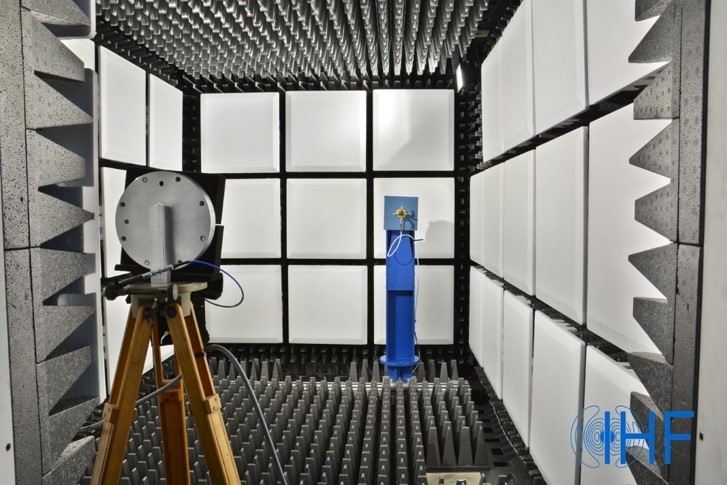


Far field anechoic chambers
There are two types of test site for the division of the distance of antenna measurement: the far field test site and the near field test site. The far field test refers to directly measuring the far field date of the under test antenna. Avoiding multipath effects and external disturbance caused by near field test, therefore, far field test is usually more reliable for antenna measurement.
There are two types of test site for the division of the distance of antenna measurement: the far field test site and the near field test site. The far field test refers to directly measuring the far field date of the under test antenna. Avoiding multipath effects and external disturbance caused by near field test, therefore, far field test is usually more reliable for antenna measurement.
For the design of far-field anechoic chamber, we must first confirm the following indicators:
Dimension of anechoic chamber: generally refers to the effective space dimension inside the chamber, or the inner dimension of the shielding.
Quiet zone: refers to the area where the clutter (including reflected waves, diffracted waves and scattered waves) in the chamber has the least interference. The dimension and shape of the quiet zone are related to the type of chamber, the operating frequency, the characteristics of absorbers and the required reflection level.The quiet zone of a rectangular anechoic chamber is a cylinder on the longitudinal axis of the anechoic chamber. The diameter of the quiet zone D can be estimated by the following formula: D≥Rλ/2.R: the distance between the transmitting and receiving antenna under the far-field conditions.λ: the operating wavelength can be seen from the formula that the dimension of the quiet zone decreases along with the operating frequency increases.
Reflectivity level:The definition of reflectivity level is the ratio of the equivalent reflection field to the direct field. The equivalent reflection field refers to the sum of the clutter interference fields in the anechoic chamber. The reflection level of any point in the chamber is related to the characteristics of absorbers, the structure of the chamber, the directivity of transmitting and receiving antenna, operating frequency, polarization of the antenna, and other related factors. Accurate calculation is rather difficult; therefore, it is usually measured by experiment.
Cross polarization characteristics:Cross polarization refers to the magnitude of the polarization components which are orthogonal to the original polarization characteristics in the transmission process of electromagnetic wave. It characterizes the polarization purity of electromagnetic wave. It must be noted that the cross polarization characteristics referred to here are different from the cross polarization characteristics of the transmitting and receiving antenna themselves. The former is caused by the asymmetry of the chamber (including material properties), while the latter is caused by the inadequate processing accuracy of the antenna. Generally, a pair of antennas with excellent orthogonal polarization performance is used to measure the cross polarization characteristics of the anechoic chamber. In order to ensure the certain test accuracy, the cross polarization isolation of the source antenna should be more than 35 dB, and the value of the anechoic chamber should be about 25 dB.
Multipath loss uniformity:It refers to the non-uniformity of the transmission path loss of electromagnetic wave in the chamber, which is particularly important for the measurement of circularly polarized antennas. Because if the path loss in the chamber is different, though the circularly polarized wave is emitted through the transmitting antenna, it becomes elliptically polarized wave when it reaches the receiving point, which obviously brings errors to the measurement. This non-uniformity is generally limited to ± 0.25dB.
Field strength amplitude uniformity:
It refers to the non-uniformity of field strength amplitude on the aperture of antenna under test in the quiet zone when the source antenna illuminates. Generally, the lateral amplitude of quiet zone should not exceed ± 0.25 dB and the longitudinal amplitude should be within 2 dB.
Frequency range:The lower limit of the operating frequency range in the quiet zone depends on the width of the chamber and the height of the absorbers. And the upper limit depends on the length of the chamber and the requirement for reflectivity level in the quiet zone.
Selection of absorbers
The performance of microwave anechoic chamber is not only related to the rational design, but also related to the performance and lining of absorbers. For the microwave anechoic chamber design, the reflectivity and lining of absorbers on each wall are selected according to the required reflectivity level in the quiet zone. The shape of the absorbers is made into a cone with cone angle of smaller than 24˚. The purpose is to improve the matching between the absorber and the space, reduce the reflectivity, and thus increase the absorbability. The absorbability of absorbers is related to the total height of materials. The new MT series microwave absorbing materials introduced by Comtest are widely used in the microwave anechoic chamber industry and deserve our attention. This absorbers can meet the testing requirements of reflectivity level in microwave anechoic chamber.
RFT can customize far field chamber configuration according to customer's requirements.


Copyright © RuiFeng RF Technology (Shanghai) Co.,Ltd 沪ICP备2021035661号-1